Università di Bologna
Dipartimento
di Astronomia
GUIDO HORN D’ARTURO The “black drop” phenomenon and astigmatism.
(Pubblicazioni
dell’Osservatorio astronomico della R. Università di Bologna, vol. I, n.3, 1922)
Italiano
Bibliography
Chapter I
ORIGINS AND PHASES OF THE “BLACK DROP” PHENOMENON
Previous
theories – Apparently, the
phenomenon of deformation of the edges perceived by the eye to a large or small
degree and with a fair light and distance around the place of apparent or
actual contact between two bodies, began to be investigated in 1761, after the
first transit of Venus across the solar disk was observed with adequate
instruments[1].
The first
observers called it “gutta nigra”, (dark ligament, black drop, ligament noir,
Tropfen, etc.) and formulated a number of hypotheses in order to explain it.
Many believed that this phenomenon originated in the sky and thus had celestial
causes; others attributed its origins to observing instruments. In this paper,
I will have the chance to mention either one or the other of the following
causes: 1) Irradiation of sunlight; 2) Atmosphere of the Planet; 3) Turbulence
of the Earth’s atmosphere; 4) Diffraction of light and its effects on the
images that form in optical instruments; 5) Spherical aberrations of lenses and
eyepieces 6) Imperfect adjustment of the eyepiece 7) Polyopia.
Undoubtedly, none
of these causes should be put aside while studying the “drop”, because each
cause can partly give rise to some of the numerous aspects that are summarised
by this single word. On the other hand, even their simultaneous action does not
succeed in justifying the complex but logical sequence of all the
phases, since some of them have always escaped the observers’ attention. Thus,
in order to reconstruct the whole phenomenon, we should use data from different
sources choosing only those details in the astronomers’ descriptions that were
clearly observed, while leaving out all the others.
To compensate the
rarity of this phenomenon – which is getting rarer due to frequently
unfavourable atmospheric conditions – and simplify astronomers’ research into
its nature, Struve suggested to reproduce the phenomenon artificially by
placing conveniently overlapping bright and dark disks far from the observer.
The most authoritative tester of this method, G.van de Sande Backhuyzen[2]
concluded, on the basis of his telescopic observations of the artificial
transit that the “drop” resulted from the diffraction of light through the
objective lens. His interpretation immediately found imitators and followers
and today, after almost fifty years, it is still generally[3]
agreed that this phenomenon is due to the cause pointed out by Backhuyzen. He also considered the
idea of polyopia, but only mentioned it as playing a minor role: “Ich glaube
mich deshalb berechtigt, zu constatieren, dass für mein Auge und für die von
mir angewandten Fernrohre die Polyopie nur eine untergeordnete Rolle bei der
Bildung des schwarzen Tropfens spielt”[4] and further on:
“...glaube ich doch, dass die Diffraction die Hauptursache ist, und will deshalb
auch bei den anderen Phasen des Venusvorüberganges seinen Einfluss bestimmen”.[5] Yet, even if these
experiments were carried out without a telescope, i.e. by observing the disks
with the naked eye and thus without the intervention of instrumental diffraction,
the phenomenon would have still been observed so that those in favour of the
diffraction theory would have been forced to look for another cause and
precisely, as I will try to demonstrate, an extremely common eye defect,
namely, astigmatism.
Sturm’s Theorem – The total effect
of the refracting means of the astigmatic eye can be explained – as with the
spherical eye – by placing a single ideal surface about 2 mm behind the front
surface of the cornea (reduced eye). Usually, in the astigmatic eye, this ideal
surface presents the maximum radius of curvature in a slightly inclined section
with respect to the line of sight and the minimum radius in a section
normal to the one above. In a rarer occurrence, the section of minimum radius
lies on the plane of the line of sight. Generally, although there are also
oblique directions, the maximum and minimum sections of curvature remain
orthogonal.
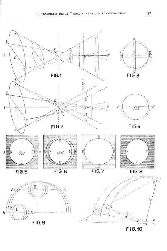
Sturm’s[6]
theory of caustic surfaces states that if the chief ray of a sheaf radiating
from an infinitely far point usually intersects at point O (pag. 57
Fig.1) with a toric surface – circularly limited by a diaphragm also centred at
point O, where the sections of maximum curvature AB and minimum
curvature CD intersect at a right angle – the rays of this sheaf refract
so as to converge in two orthogonal focal lines passing through f and F.
The former lies on the plane of the section of minimum curvature CD
and contains the focus of the section of maximum curvature AB
whereas the latter lies on the plane of the section of maximum curvature
AB and contains the focus of the section of minimum curvature CD. If
the planes are perpendicular to PP’ but do not pass through f
or F, the resulting images will generally be ellipses either with their
major axis parallel to CD - if they are on the left of point T
- or parallel to AB - if they are on the right of point T.
If the plane passes through T, the resulting image will be circular since
point T lies halfway between f and F, but closer to f.
Now, the fact that the pupil’s diameter is automatically reduced to its
minimum in very bright light – thus getting closer to the ideal condition
described by Sturm’s Theorem – can be applied to the real case of the
astigmatic eye. Moreover, if the surface of maximum curvature of this eye is parallel
to the vertical and the minimum is parallel to the horizontal (as in Fig.1
pag.57), the image of the infinitely far point thrown onto the retina will have
the shape of a straight line segment. More precisely, if the retina - normal
with PP’ - passes through F, the line segment will be vertical whereas through f, it will be horizontal.
Apparent deformation of celestial bodies – Given the shape
taken by the image of a point on the retina of an astigmatic eye, it will be
easy to reproduce the image of a celestial body thrown onto a sphere in the
shape of a circular disk. Instead of a circle, this image will correspond to
Fig.3 or Fig.4, depending on whether the retina contains the focal line F
or f. The two semi-circumferences DBD’ and DCD’ - forming
a whole circumference when they both have their centres in O –
contribute in all their length and with no deformation whatsoever to form the
profile of the deformed image when their centres are shifted to O’ and O’’,
respectively. In order to close the profile of the deformed image, we need two
straight lines RS and R’S’, both as long as the focal line and
tangent to the circle at points D and D’. In other words, it is
possible to obtain the deformed image ARSA’S’R’ directly from the
circle, provided that each point of it dilates in either directions and
parallel to the straight line AA’ (which we shall call maximum radial
deformation line), thus turning into a straight line segment as long as the
focal line.
Yet, a closer look
at this phenomenon shows that deformation caused by astigmatism is also
subordinate to the relationship between the luminous intensity of the image and
that of the background on which it is cast. Indeed, Fig.5 shows how a bright
disk on a black background would appear to a spherical eye: we distinguish a
white and a dark area, both bordering on circle BDCD’. The dilation
caused by astigmatism, whose line of maximum radial deformation is AA’,
will take the circle BDCD’ both to BECE’ (Fig. 6) – thus becoming
the new external border of the dilated bright area – and BFCF’ – thus
becoming the new internal border of the dark area, dilated in turn. As a
result, we have the original whiteness characterising the internal area BFCF’
and the original darkness characterising the area external to BFCF’, respectively,
whereas the area between the two curves BECE’ and BFCF’ shows a
mixed colour made up of an equal measure of black and white. Furthermore, if
the brightness of the luminous disk overcomes the darkness of the background,
the astigmatic eye will see Fig.5 deformed into Fig.7; on the other hand, if
the surrounding blackness definitively prevails on the weak light of the
internal area, such eye will see Fig.5 deformed into Fig.8. Only extremely
sensitive eyes will also be able to distinguish the intermediate coloured area
comprised between the blackness of the background and the brightness of the
image.
Two well-known
examples concerning the prevalence of light over darkness are available to
astronomers, i.e. the solar image projecting on a dark background sky (through
the obscuring device) and the dark faces of inferior Planets projecting on the
solar disk. Since in both cases powerful sunlight takes over nearby darkness,
the Sun’s disk appears dilated while the Planet’s disk appears contracted. In
order to avoid any confusion with the phenomenon known as “irradiation”, I
would like to point out that these deformations have – in the radial sense – their maximums and minimums placed
symmetrically according to the observer’s astigmatism.
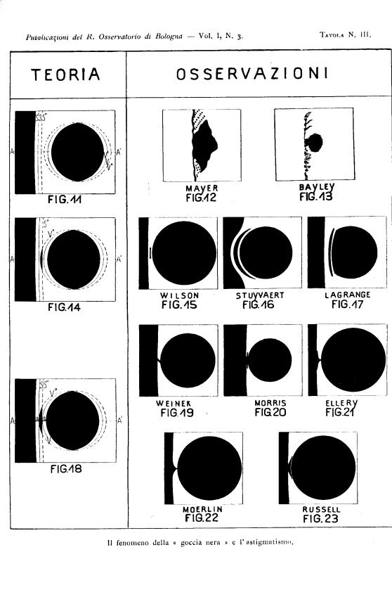
Apparent contacts of celestial bodies – Let AA’ in
Fig.11[7]
be the line of maximum deformation coinciding with the line joining the centre
of the Sun to the centre of the Planet. Continuous
lines S and V
outline the actual limits of the two disks while terminators S’ and V’
outline their apparent limits and line segments S’’ and V’’ their
latent limits. By apparent limits, I
mean those perceived by the astigmatic eye (instead of actual limits, perceived
only by the spherical eye) whereas by latent limits S’’ and V’’ I mean those
that are not visible until the two disks are far away from each other, as in
Fig.11, but that will manifest themselves during the transit, either preceding
or following the contact, as I shall now describe. The four thicknesses SS’,
SS’’, VV’ and VV’’ are identical with regard to celestial bodies,
which are at the same distance – or virtually so - from the observer.
We know
that the light intensity of the areas comprised between limits S’S’’ and
V’V’’ competes with that of the solar disk. Yet, as the two bodies make
contact and latent limit V’’ crosses latent limit S’’ (Fig.14),
the crescent -
a mixture of two parts of darkness and one of light - comprised between such
limits will be significantly darker than the surrounding area (although its darkness
will equal neither the background sky nor the dark face of the Planet). This
crescent, which is limited by the Planet’s edge, on the left of those observing
Fig.14, and by the Sun’s edge, on the right, will be completely surrounded by
light.
If we follow the
Planet during its motion of egress from the solar disk, as it reaches the
furthermost point of the latent limit V’’ in contact with S (and
consequently V with S’’), Fig.18, we immediately perceive
continuity among three dark regions: 1) background sky, 2) crescent or detached
limb, 3) Planet’s disk, because of the simultaneous appearance of two identical
straight line segments “a”, which have given this phase – as well as the
whole phenomenon – the name “dark ligament” or “black drop”. This phase is
totally justified by Sturm’s Theorem. According to it, each luminous point
produces a straight rather than a point-like image on the retina of the
astigmatic. Consequently, the furthest point of the detached limb of the Planet
covers a point on the actual edge of the Sun so that there will be a luminous
line segment of 2a in length rather than a luminous point on the retina.
Such line segment lies on the line of maximum deformation AA’ with its
midpoint where V’’ meets S; the same can be said of the length
and position of the luminous line segment whose midpoint is where V
touches S’’, which will disappear when the furthest point on the actual
edge of the Planet will be occulted by the right edge of the detached limb.
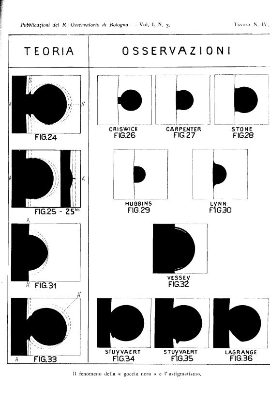
As the Planet
moves forward in the same direction, an increasing number of luminous points on
the actual edges of the two bodies S and V will be occulted and
the corresponding images of the luminous line segments will be replaced by an
equal amount of dark line segments, as shown in Fig.24, until the Planet -
before reaching the actual solar limb with its centre, (Fig.25) - takes the
peculiar shape of a capital “D”. By following the Planet until its complete
darkening on the solar disk, it is possible to reach, through different stages
of easy geometrical construction, the occultation of a single point on the
actual solar limb (Fig.25 bis), where one of the straight line segments in
Fig.18 reappears.
Although in the
above-mentioned six figures the line of maximum deformation passes through the
centres of both disks, this does not always occur. Indeed, if the line AA’
is inclined with respect to the line joining the centres, in an advanced phase
of this phenomenon the ligament will assume an oblique direction (Fig.33) that
will be confirmed further on by the observers’ descriptions.
In a
peculiar case, the line of maximum deformation could be orthogonal to the line
joining the centres (Fig.31). Hence, it would be possible to better witness the
flattened shape of the visible part of the Planet (Fig.31) when half of the
Planet’s circumference is off the Sun’s limb rather than when it is fully on
the disk of the Sun.
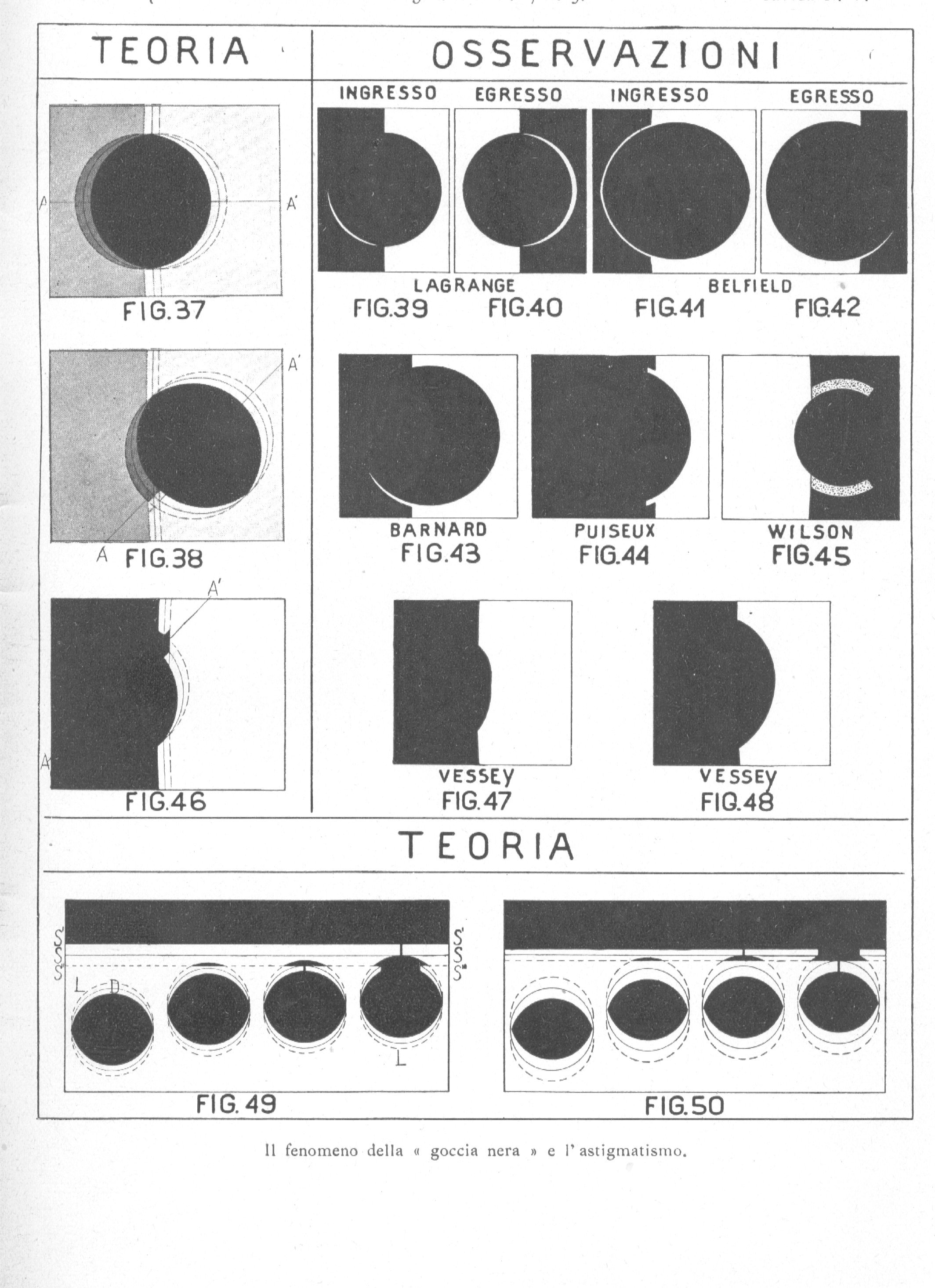
Halos – Until now we have imagined that the background
sky and the dark face of the Planet show the same degree of darkness through
the obscuring device, which protects the eye from excessive sunlight. However,
in some cases, i.e. when using no protection or just a thin obscuring device
when the Sun is very low on the horizon or veiled by fog, the background sky
looks considerably less dark than the dark face of the Planet. In these cases,
being the Planet’s disk partly on and partly off the solar disk (despite all
research, there is no reliable observation of the Planet completely off the
Sun), the astigmatic eye will perceive a crescent around the non-overlapping
part. This crescent consists of mixed light and looks clearer than the Planet
and darker than the background, as in Fig.37, so that the observer will have
the impression that the Planet’s disk is surrounded by an atmosphere.
As to the crescent
opposite the one mentioned above, VV’’ (Fig.37), we have always assumed
that the sunlight is so bright that it cancels the effect of the Planet’s dark
colour. Yet, in some cases, extremely sensitive astigmatic eyes are able to
distinguish even a slight difference between the sunlight and the light of the
crescent V’V’’, thus regarding
the Planet – especially when it is fully on the solar disk – as surrounded by a
halo. As we will see further on, some observers considered this halo weaker
than the Sun while others considered it so bright that it looked shinier than
the very Sun.
Of course, when
the line of maximum deformation AA’ is inclined with respect to the line
joining the centres, the appearance of the halo surrounding the non-overlapping
part of the Planet corresponds to Fig.38.
Chapter II
COMPARISON WITH THE OBSERVATIONS
Detached limb – This phase, unlike
the others, was clearly recognized by a small number of observers. Pingré was
the first to mention it. Having witnessed both transits of Venus in 1761 and
1769, he was very surprised to see that the phenomenon observed in the first
transit had not occurred again in the second. In his own words[8]:
“At the exit of Venus in 1761, the limbs, being not yet in contact, and even
sensibly distant asunder, I saw as it were a dark spot detach itself from
Venus, and gain the limb of the Sun;...at which instant I estimated the
internal contact. Many have this year seen the same phaenomenon at the total
entry of Venus. I was in expectation of it; neither I nor my associates
perceived any such thing”.
Although the
description of the missing “dark spot” may puzzle the reader, it seems that he
clearly saw a detached limb and that, immediately after, during the sudden
appearance of the drop, he regarded the “spot” as reaching the solar limb due
to proper motion.
Chronologically,
the second mention – which is much more explicit and also confirmed by a
drawing reproduced in Tab. III (Fig. 15) – was by Wilson, who observed Venus transit
of 1874 in Mornington (Australia). The detached limb is represented by a
straight line segment that he describes as follows[9]:
“there first appeared a small dark object flickering backwards and forwards
between Venus and the edge of the Sun”.
During the
following transit of 1882, Belgian astronomers Stuyvaert and Lagrange observed
the phase of the detached limb in Texas and Chile, respectively [10].
Stuyvaert’s drawing[11]
- reproduced in Fig.16 - lacks a description but clearly shows the Planet’s
limb completely surrounded by sunlight. The same can be said of Lagrange’s
drawing[12]
(Fig.17), which comes with the following description[13]:
“Un filet lumineux vient couper la goutte noire. Le disque de Venus semble se
separer du bord du Soleil, mais entre ce disque et le bord il y a un filet noir
à peu prés concentrique avec le Soleil”.
These two
latter drawings – remarkable for their rarity – undoubtedly confirm the
appearance of the detached limb and hence, in theory, they should show the
curvature of the Planet on the concave edge of the crescent and the curvature
of the Sun on its convex edge. However, both edges of the crescent appear
equally curved i.e. in the first drawing both curvatures correspond to those of
the Planet whereas in the second they both correspond to those of the Sun.
Finally, the last
mention of such phase - that none of the previous theories could justify –
comes from J.Tebbutt, a tireless observer of transits, who fails to illustrate
his words with a drawing but describes the appearance of the first internal
contact as follows[14]:
“...Just at the time, when I expected geometrical internal contact to take
place, the Planet became somewhat pear-shaped, its limb being connected with
that of the Sun by a triangular black ligament, whose base was on the Planet,
and its apex on the solar limb... The ligament suddenly broke at the same time
and for fully 14 seconds the vibrations were so great that the triangular
ligament was repeatedly seen separated both from the disc of the Planet and
the limb of the Sun”. Rather, I tend to believe that it was precisely the
extraordinary and almost unbelievable phenomenon of the detached limb that gave
the observer the impression of such a turbulent atmosphere. Otherwise, amidst
such meteorological turbulence, it should have been impossible for him to
observe the phase of the ligament only a few seconds earlier and so accurately
and even notice its triangular shape and the position of its base and apex.
Furthermore,
there is a significant number of observers – probably half of those whose
descriptions I read (see Table at pag.43) – who point out at least two phases
of this phenomenon: 1) geometrical contact, 2) appearance (or disappearance) of
the luminous ligament (in other words, the definitive separation of the two disks)
and assign them different times, sometimes using intervals longer than a
minute. Nevertheless, they do not mention a drop or a ligament but only shades
that they try to explain in different ways. Personally, I would classify these
shades as part of the phase of the detached limb, whose real nature was
perceived only by the above-mentioned very lucky few. Here are just a few
instances of those descriptions, yet many more could be added.
In 1882 in Potsdam, while
observing the ingress of Venus on the solar disk with a refractor with an
aperture of 30 cm and a magnification of 120x[15], H.C. Vogel spotted a
luminous ligament (ein ganz feiner Lichtfaden) between the Sun and the Planet
and wrote: “Von Trübung zwischen Venus und Sonnenrand war zu der Zeit keine Spur
sichtbar; sie bildete sich erst kurze Zeit darauf, war breit und dunkel am
Sonnenrande, weniger breit und weniger intensiv an der Peripherie der Venus. Diese
Trübung verschmälerte sich in dem Maasse als die Venus weiter eintrat, und
verschwand ziemlich rasch. Eine Tropfenbildung fand nicht statt”. In other words,
this is a definition of the detached limb, which gets thinner and thinner as
the area formed by the overlapping latent limbs fades away.
Similarly, in the
same year Jas. Williamson, Director of the Kingston Observatory, observed the
ingress of Venus on the solar disk with a 6¼ inch Alvan Clark equatorial[16]:
“For a little while after”, (i.e. after what he regarded as the geometrical
contact), “the limbs seemed slightly to separate, a dark shade occupied the
narrow interval between them, extending a little way on each side of the former
points of apparent contact... there was nothing of the so called black drop,
but only the dark shade already referred to”. About egress, he said: “The dark
haze seen at ingress in the morning began at this time to be again observed at
egress, but the interval during which it continued, and discontinuity was
noted, was much shorter than in the forenoon”.
In addition, also Dunér and
Lindsted clearly deny seeing either a drop or disks’ deformations while
observing Mercury transit on May 6, 1878[17] in Lund: “Eine
Verzerrung des Bildes oder eine Tropfenbildung war diesmal ebenso, wenig zu
sehen wie beim Durchgange von 1868”. Yet, they both give two times for the moment of
internal contact:
|
|
|
|
|
Geometrical
contact...................
|
4h 6m 39s, 0
|
6m, 41s, 0
|
|
Luminous
ligament....................
|
6 52, 0
|
6 52, 0
|
Clearly, if the
geometrical contact occurred at 6m 39s and 6m 41s, respectively, it was already
over thirteen or eleven seconds later. Yet, having not seen any light between
the two disks, the observers were late in declaring that the separation
actually took place. I could quote many more cases with longer intervals,
during which the observers saw unclear shades that prolonged the duration of
the contact up to 3 minutes[18]
between the two edges.
“Drop” and
“Chinaman’s cap” – Any apparently foreign
shape or shade showing between the two disks and affecting their geometrical
contact is generically called “ligament” by observers. However, this expression
should define the straight line segments in Fig.18, because they are the only
ones that effectively join the two disks and look like real links suddenly
stretched between the closest areas of the two celestial bodies when a luminous
point of one or the other edge appears occulted to the astigmatic eye. The first
observers rightly called this sudden phase “fulmen” – a very appropriate term
when considering that the remainder of this phenomenon takes place very slowly
and smoothly.
Among the great
range of illustrations of the “drop”, some only consist of a straight line
segment while others of a small extension whose end closest to the Planet
appears bigger. By merging with the advanced limb of the Planet, this end gives
the whole image a pear shape, which has been frequently mentioned during
the different transits of Venus and Mercury.
Generally,
according to observers, the direction of the straight line segment seems to be
lying on the line joining the centres of the two bodies. Even though this can
sometimes occur, it is not strictly necessary because it depends on the
direction of the line of maximum deformation of the observing eye, which could
be lying in turn. Yet, only in Weinek’s drawing[19]
(see Fig.19) the ligament is considerably inclined with respect to the line
joining the centres, as displayed in theoretical Figure 33, in Table IV.
The phase of the
detached limb being crossed from side to side by a straight line segment
(Fig.18) was observed and drawn almost exclusively by English astronomers, who
named this phenomenon “Chinaman’s cap”. I reproduce, in a slightly enlarged
version, one of the drawings by Morris[20]
(Fig.20), who observed Venus transit of 1874 in Glenrowan (Australia) - with an
8 ½ inch Browning reflector– since it is the only one throughout
literature which meets the requirements of the astigmatic theory as far as this
phase is concerned. Unfortunately, Morris did not comment his excellent
drawing, which is very effective nonetheless.
The drawings by
Ellery, Moerlin and Russell - who were also observing the same transit in 1874[21]
- are more similar to the “Chinaman’s cap” but not as close to the actual
aspect of the phase. In partial agreement with the mentioned theory, see Fig.21,
22 and 23. Fig. 21 and 22 show the lack of the line segment nearest the solar
edge, while Fig.23 shows the lack of the line segment nearest the Planet,
although it succeeds in clearly depicting the detached limb.
Undoubtedly, the
phase shown in Fig.18 is also hinted at by the astronomer Leygue, who noticed
some dark fringes between the two disks[22]
during Venus transit of 1882: “Ces franges etaient traversées par un ligament
noir tante que le contact n’avait pas lieu et elles devenaient continues à ce
moment”.
Weakening and strengthening of the Planet’s limb – These two phases,
which can be considered opposite, are reproduced in Fig.25 and 31 (Tab. IV) and
can be obtained with a simple construction, by taking into account the
observer’s astigmatism, whose line of maximum deformation is presumably along
the line joining the two celestial bodies in Fig.25 and normal with it in
Fig.31. There are numerous examples of the first shape that someone called
capital “D”. Higgins, who noticed it during Mercury transit of 1868,
drew Fig.29 and gave the following description:[23]
“The spot (i.e. the disk of the Planet) appeared distorted, spreading out to
fill up partly the bright cusps of the Sun’s surface between the planet’s disc
and the sun’s limb. This appearance increased as the planet went off the sun,
until when the disc of the planet had passed by about one third of its
diameter, it presented the form represented in the diagram in which the margin
of the disc, from points at the end of a diameter parallel to the sun’s limb,
instead of continuing its proper curve appeared to go in straight lines up to
the limb, thus entirely obliterating the cusps of light, which would otherwise
have been seen between the planet and the limb”. Such description clearly
points out the progressive invasion of the bright solar cusps by the “drop”,
which becomes increasingly big at egress of the Planet.
In addition, as
regards the mentioned Mercury transit (1868), I reproduce another four drawings
of the “D” shape by W.T.Lynn[24],
G.S. Criswick[25],
J.Carpenter[26] and
E.J.Stone[27] in Fig. 30,
26, 27 and 28, respectively. The latter three, being more consistent with this
theory, show the deformed parts in their places, as in the geometrical
construction.
Other observers
mention this phase without going into details, e.g. Russell[28]
(Mercury 1881): “Mercury assumed a “D” shape”. It is worth pointing out
that the observations of the “D” shape that I have quoted so far refer
to Mercury although Liversidge[29]
noticed the same appearance also during Venus transit of 1874: “...Venus
appeared to be nearly one third off the Sun’s limb; there was just the
slightest trace of distortion or tending to the D -form, retained until
the Planet was half off; hardly perceptible”.
The observation of
the opposite phase, shown in Fig.31, is rarer. During Mercury transit of 1878,
it was observed, at ingress, by Geelmuyden[30]
at Cristiania Observatory with a 7 inch refractor. He described it as follows:
“Einschnitt als Spitze gesehen, nach einer Skizze einen Winkel von etwa 120°
einschliessend”. During Mercury transit of 1868, Oppolzer[31] saw it at egress with a
4 inch instrument and claimed: “Den Ausschnitt den die Scheibe des Mercurs eine
Minute vor der aüsseren Berührung in der Sonnenscheibe bildete, schien nicht
entsprechend einer runden Scheibe, sondern sehr merkbar conisch, und blieb so,
kleiner werdend, bis zum Moment des Verschwindens”.
Fig. 32
illustrates the observation carried out by Vessey[32]
in Woodford (Venus 1874); apart from the flattening, this drawing also shows
what he calls “halo” - a subject that I shall discuss in next chapter.
Morso di Faravella, who took part to the Italian
expedition to India led by Tacchini[33],
found the phenomenon outlined in Fig. 25 bis: “At that moment
(first external contact) I did not see a circular segment on the Sun's edge but
a shrp tip that soon turned into a circular arc”. And about the advanced limb
of the Planet, which was about to leave the solar disk: “...the phase gradually
decreased and, by then very tiny, seemed to recover
a point-like shape as in the first contact, etc.”.
Halo of
the overlapping Planet – Although the Planet’s disk, which is completely
on the Sun, appears deformed because of astigmatism, it does not stop being a
symmetrical image (Fig.11); the overlapping of the dark limbs of the Planet and
of the bright background of the Sun results in a sort of halo of maximum
thickness along the line of maximum deformation and equal to zero in an
orthogonal direction to it. Such halo cannot be as bright as the Sun and is
considerably less dark than the Planet, to the extent that many mistook it for
its atmosphere, lit by sunlight from behind. Some regarded it as brighter than
the Sun, some did not see it at all whereas others saw it either as less bright
than the Sun or of different colours such as orange, violet, etc.
Undoubtedly, the
halo might have looked brighter than the Sun and Huggins[34],
who had the chance to see it with an 8 inch telescope (120-220x magnification)
during Mercury transit of 1868, authoritatively confirms it: “Whilst carefully
examining the immediate neighbourhood of the spot (the Planet’s disk) for the
possible detection of a satellite, I perceived that the Planet was surrounded
with an aureola of light, a little brighter than the solar disc”. And further on:
“The aureola was not sensibly coloured, and was only to be distinguished from
the solar surface by a very small increase of brilliancy”.
I would also like to quote the last period of Huggins’
commentary to his observation of the halo, where he recalls similar phenomena
occurring during different transits before 1868: “Similar phaenomena have been
observed at some former transit. A sort of ring of faint light was seen by
Plantade at the transit of 1736; also by Proserpin; also by Flaguergues in
1786, and in 1789 and 1799. He calls it “an anneau lumineux”. Mechain Messier,
Fritsch, and Syffler observed a similar phaenomenon. It is also described by
Schroeter and Harding during the transit of 1799. In 1832 Dr. Moll saw it as “a
nebulous ring of a darker tinge approaching to a violet colour”. Some of these
observers appear to have considered the aureola to be slightly brighter and
others as in a small degree darker than the sun”.
The brighter halo was also observed by Browning[35]:
“slightly brighter than the solar disc”. Also Downing, during the transit of
1878, claimed: “An appearance of a ring slightly brighter than the Sun was
visible round the Planet”.[36]
Unlike the
above-mentioned astronomers, Krone[37] observed it not only
round Mercury but also round Venus: “Jetzt schwebte die kleine Venusscheibe
frei in der von jetzt an laengere Zeit hell leuchtenden Sonnenscheibe, rings
umgeben von einem heller als die Sonnenflache leuchtenden Lichtkreise”.
Karlinsky[38]
and Pohl[39]
perceived the halo as less bright than the Sun, Borrelly[40]
as “grisátre” and Gilbert[41]
as “violet”.
Clearly, if the phenomenon depends on astigmatism, the
halo should appear clearer than the Planet and less bright than the solar
surface; only 9 astronomers out of 63 who mention it perceived it as brighter;
11 perceived it as considerably less bright, while the others did not comment
on its luminous intensity.
Only Vessey illustrated in Fig. 32 the diverse halo’s
thicknesses as symmetrically decreasing from maximum to minimum. Walter Pye[42]
found that the halo was not concentric with the disk of the Planet and
mentioned “the ring being narrower (to Mercury’s edge) on the side next the
Sun’s limb”.
In the Table at pag.43, it is worth noting the greater
frequency of observations of the halo around Mercury rather than Venus, whereas
the opposite is true of the halo, which seems to surround the Planet off the
Sun – a subject that I shall deal with in the next paragraph.
However, if the sunlight completely overcomes the
darkness of the overlapping Planet, it will not be possible to
distinguish the halo from the luminous background and the Planet will appear
symmetrically deformed as in Fig. 11. The disk will therefore no longer appear
round but oval. Fig. 12 and 13 by Mayer[43]
and Bayley[44] clearly
show this elongated shape.
Nobody better than B. Ferner[45]
briefly but accurately described the sight that he witnessed in 1769 i.e. the
extreme transformation of the dark image of Venus about to come off the
ligament that restrained it in order to appear free and fully overlapping the
Sun: “The diameter of Venus, which was perpendicular to the Sun’s limb appeared
the greatest while Venus was passing over the Sun’s limb; but after Venus had
passed the sun’s limb, the same diameter appeared the smallest; so that Venus
presented himself in both these cases under an oval form, but in contrary
directions”. Here, the same cause gives rise to the consecutive “drop” and
flattening phases as shown in Fig. 24 and 11.
During last Mercury transit of 1914, the astronomers of
Greenwich Observatory measured the diameters of the Planet overlapping the Sun
from different position angles without finding remarkable differences (they do
not say how they kept their line of sight with respect to the filar micrometer – an essential element in
this type of measurements), but Jonckheere[46]
said about his colleagues: “At 22h 50m Mr.Bryant observed that the horizontal
diameter of the Planet looked the smaller. At 0h 5m Mr.Furner was of the
opinion that the identical diameter appeared the larger and I had personally
the same impression. This may be an optical illusion”.
I shall discuss the micrometric
measures of the diameters of Mercury recorded by Belgian astronomers in
relation to the position of the line of sight at pag.47.
Halo of the non-overlapping Planet – Despite all the
attempts, nobody has ever succeeded in clearly seeing the Planet in its
inferior conjunction, unless a small limb next to the Sun revealed its
presence. By following this dark line segment, some astronomers observed the
supplementary limb projecting onto the sky, surrounded by a faint light.
The observer's astigmatism can
explain this light whenever the disk of the Planet appears darker than the
background sky – a frequent occurrence when using low intensity obscuring
devices.
Thus, a region takes shape – as for Fig. 37 – next to the
disk and the background sky but less dark than the disk and less bright than
the sky. The astigmatic will then see the Planet surrounded by a halo that he
will regard as clearer than the Planet.
The region of the overlapping limbs is not a circular
ring but presents – as in Fig. 37 – a maximum thickness along the line of
maximum deformation and virtually a zero thickness in the orthogonal direction
to it. The crescent shape that reveals the real nature of the phenomenon is
largely confirmed by a significant amount of information in the astronomical
annals, where the appearance is generally ascribed to the atmosphere of the
Planet. Fig. 40 shows Lagrange’s drawing[47],
which refers to the egress of Venus from the solar disk during the 1882 transit
and is described as follows: “Le bord exterieur de Venus est eclairè; l’image
est admirable et les cornes parfaitement nettes”
However, the presence of the crescent’s maximum thickness
on the line joining the centres is sheer chance whereas, generally, the line of
maximum deformation forms an angle with such line, thus generating asymmetrical
halos, as shown in Fig. 39 also by Lagrange and in Fig. 41, 42 and 43 taken
from the descriptions by Belfield[48]
and Barnard[49]. About Fig. 39, Lagrange
says: “On voit le disque de Venus sur le fond du ciel, a gauche et en bas une
aureole lumineuse blanche due sans doute à l’eclairement de l’atmosphere de
Venus”. The line of maximum deformation and the line joining the centres incessantly
vary their reciprocal position so that if they coincide at the first contact,
they generally do not at the second.
Even Langley[50],
during Venus transit of 1882, was struck by the mentioned asymmetry: “The
centre of this bright marginal segment was estimated, from a rough sketch made
at the telescope, as being about 30° on one side of a line joining the centres
of the Sun and Planet, and its asymmetrical position with reference to the
horns was conspicuous”. Wright[51],
in his description of Venus transit of 1874, says: “...this halo (after the
third contact) gradually became brighter and was not so uniform as at ingress,
but most distinguishable on the NE quadrant of the Planet”. During the same
transit of 1874, Onslow[52]
illustrates – with two beautiful drawings better than with his description –
the asymmetry that characterises the halo off the Sun. I believe it is
also worth mentioning Puiseux’s[53]
words, from which I infer that the aspect described by him can be represented
in Fig. 44: “Le fond du ciel est bleu, les images sont brillantes et calmes. Un quart environ du
disque de Vénus est déjà sur le Soleil. Le cornes se terminent avec une netteté
parlaite, mais de leur extrémité se détache une auréole pále qui entoure Vénus
sur une étendue de 5° á 6° vers l’extérieur, à partir des pointes
d’intersection de sa circonférence avec celle du Soleil. Je m’assure à
plusieures reprises que l’arc lumineux n’est pas complet. Je substitue au
grossissement de 110 employé jusqu’ici, un oculaire grossissant 160 fois.
L’aspect du phénomène n’est pas modifié, non plus que par l’emploi d’un partie
plus sombre du verre gradué”.
The halo had been
seen in a similar shape since 1761 around Venus by B.Wilson[54]
(Fig. 45). A significant number of further observations could be quoted, yet no
one except Russell and Schiaparelli mentioned the moderate darkness of the sky
in comparison to the Planet – an essential condition for the appearance of this
halo. Ten minutes after the first contact, Russell[55]
saw “the whole of the Planet...that portion of it without the Sun, appearing on
the bright sky near the Sun’s limb”; and after another five minutes he
saw the halo – of which he also provides a figure. It is possible to deduce
that the sky was less dark than the Planet during Schiaparelli’s observations[56]
(Venus 1882), from the fact that he did not protect his eye with obscuring
devices: “From then on" (i.e. after
the first contact) "there was a restless movement
of more or less dense vapour through the hole in the clouds. When half
of the Planet had already entered it, a clearer moment allowed me to
see Venus atmosphere in the shape of a bright arc in the dark
region off the Sun".
Advocates of previous theories did
not even try to explain the presence of this halo, while observers
unmistakingly attributed it to the atmosphere of the Planet – a very unlikely
hypothesis, considering the different thicknesses that it shows.
Stuyvaert and Lagrange’s appendix – Despite
its paradoxical appearance, this shape - which was bravely published by the
scrupulous Belgian astronomers exactly as they saw it - is nothing but a
logical consequence of the cause that was used to explain the other phases. The
more divergent the line of maximum deformation from the line joining the
centres, the clearer the shape. In Fig. 33, this divergence amounts to
45°. About
his drawings, Stuyvaert[57] says: “La corne
septentrionale (i.e. of the Sun) se termine en deux dents en forme de scie” and
Lagrange[58]: “La corne inferieure
du Soleil empiète sur Venus tout en restant parfaitement geometrique”.
Vessey’s
“bulge” – A 60° inclination of
the line of maximum deformation with respect to the line joining the centres
causes the further limb of the Planet projecting onto the Sun to appear as
shown in Fig. 46. It shows, on an exaggerate scale, the essence of the
asymmetrical swelling that Vessey (Venus 1864)[59]
called “bulge” and illustrated in Fig. 47 and 48, describing it as follows:
“Fig.47... the Planet slightly flattened on that portion of the limb nearest
the Sun’s centre, and with a slight bulge near the northern termination of the
limb” and “Fig.48... Venus was not quite circular, the curve of the Planet’s
limb being slightly flattened on the eastern side, with a slight bulge on the
western side”.
Discontinuity
and intermittence of the phenomenon – The first critics
of the observations of the contacts found it strange that some astronomers saw
the drop’s phases while others could not find them despite looking for them
and, stranger still, that the same observer would perceive this phenomenon
during one transit, but not during the next[60].
There is an even more peculiar – though very rare – occurrence (see statistical
Table at pag. 43): the same observer, using the same instrument, sees two
internal contacts but the first is characterized by the appearance of the drop
while the second is perfectly geometrical or vice versa. Fig. 9 shows the ideal
configuration for the phenomenon to reach its maximum in contact I and to equal
zero in contact II. This occurs when the line of maximum deformation AA’
coincides with the line joining the centres in the first case whereas it is
orthogonal to it in the second case. If the two above-mentioned lines formed an
identical angle in both contacts, the duration of the contact would be the same
in each case, otherwise durations would be different.
The times below,
concerning observations dating back to 1769, are chosen from a list of
durations of internal contacts during Venus transits of 1761 and 1769, as
compiled by Dubois[61]:
|
|
ingress
|
egress
|
|
Hell.............
|
6s
|
11s
|
|
Green..........
|
40
|
48
|
|
Cook...........
|
60
|
32
|
The following
times, relative to the transit of Venus of 1874[62],
show greater differences:
|
|
ingress
|
egress
|
|
Ellery............
|
1m 30s
|
2m 22s
|
|
Whyte...........
|
2 2
|
1 52
|
|
Wilson..........
|
1 40
|
1 55
|
Quite frequently,
observers saw the “drop” only in one of the two contacts: Heraud[63]
saw it only in the first contact during both Venus transits of 1874 and 1882.
Whyte[64],
during Mercury transit of 1881, asserted that “When about two thirds of the
Planet had entered on the Sun’s disc, it assumed a pear shape”, hence: “At
egress the definition was exceedingly good; the contacts were formed without
distortion or clinging”. In the first contact of the same transit, Moerlin[65]
noticed “a cloudiness between the edge of the Sun and the Planet, before a
complete separation took place” and thus “the contacts at egress I consider
good, no ligament or bead having been seen, but a clear and comparatively sharp
contact”. Finally, during Mercury transit of 1914 Storey[66]
observed: “The first internal contact was well seen, the black drop phaenomenon
being very persistent”; while about the second internal contact he warned that
“the contact was noted on this occasion as quite clear, no ligament of any kind
being visible”.
Before closing this chapter, I would
like to mention a case of intermittent apparition of the ligament, which first
formed and later dissolved from the observer’s sight. The observer put it down
to atmospheric turbulence, yet intermittence never fails when, during
observations, the astigmatic observer changes the position of his head and,
consequently, of the line of sight - as it generally happens to those whose
body and head have been in an uncomfortable position for a long time.
As a matter of fact, in two consecutive figures of Venus
egress (1874), Russell[67]
clearly shows, respectively, the presence of the “drop” and Venus disk (which
is closer to the Sun than in the previous instant) separated from the Sun by a
very distinct interval. Figures aside, here are his words: “During one of these
(moments of bad definition) at 3h 53m 53s, 59 the limb of the Planet nearest
the Sun’s limb seemed to be in a state of vibration, as if portion of its
blackness were jumping over to the Sun, which lasted only a few seconds, the
vibrations being estimated at 6 or 7 per second[68];
after this the limbs recovered their perfect definition[69]
and were clearly and steadily separated by a line of light, which at 3h 54m
26s, 30 could not have been more than a half a second of arc in thickness”. One
cannot help being surprised by the fact that the atmospheric turbulence
pictured in Figure 1 could be followed after only 32 seconds by such a quiet
that allowed either limbs to maintain a perfect definition.
Observations statistics– The numerical table in the following page contains a
statistical survey of 504 descriptions of Mercury and Venus transits on the
solar disk and includes the last four Venus transits and seven Mercury
transits, starting from 1868. The novelty and variability of the phenomenon
confused observers, who consequently found it difficult to describe it. Hence,
descriptions are often marred by contradictions and make classification a very
difficult task. For instance, many deny having seen the “drop” but give two or
three contact times up to 60 secs. or more. Yet, in theory, to anastigmatic
eyes endowed with normal sensitivity, these contacts should last an instant or
a few seconds at most. These contradictory cases are under the column headed
“drop / seen”. I have not included those who saw the “drop” in both contacts
because they are under the column headed: “longer duration in one than the
other”, since I have never found two identical times as to the duration of
ingress and egress.
The Table does not need
further explanations. Moreover, given the numerous natural and artificial
causes that contribute to the major or minor visibility of the phenomenon, it
would be unwise to draw conclusions that cannot actually be drawn from
numerical data.
OBSERVATIONS STATISTICS
|
MERCURY TRANSITS
|
|
Years
1868
1878
1881
1891
1894
1907
1914
Total for Mercury
|
Num of observers
52
31
16
65
18
87
47
316
|
DROP
|
HALO
|
Oval shape of the Planet
|
|
|
(one internal contact observed)
|
(both internal contacts observed)
|
Overlapping Planet
|
Non-overlapping Planet with respect to the joining
line
|
|
|
seen
|
not seen
|
seen in one
|
longer duration in one than the other
|
brighter than the Sun
|
less bright than the Sun
|
no indications about the intensity
|
symmetrical
|
asymmetrical
|
|
|
18
|
18
|
0
|
2
|
2
|
1
|
15
|
1
|
0
|
1
|
|
|
15
|
5
|
0
|
0
|
2
|
4
|
9
|
0
|
0
|
1
|
|
|
6
|
3
|
3
|
1
|
0
|
1
|
3
|
0
|
0
|
0
|
|
|
31
|
7
|
0
|
0
|
0
|
0
|
1
|
6
|
0
|
0
|
|
|
8
|
2
|
0
|
0
|
0
|
0
|
0
|
0
|
0
|
0
|
|
|
15
|
18
|
1
|
2
|
2
|
4
|
21
|
0
|
0
|
0
|
|
|
13
|
15
|
1
|
8
|
1
|
0
|
2
|
0
|
0
|
5
|
|
|
|
|
|
|
|
|
|
|
|
|
|
|
106
|
68
|
5
|
13
|
7
|
10
|
51
|
7
|
0
|
7
|
|
|
VENUS TRANSITS
|
|
1761
|
13
|
5
|
3
|
0
|
4
|
0
|
0
|
4
|
3
|
1
|
0
|
|
1769
|
49
|
35
|
0
|
0
|
1
|
1
|
0
|
1
|
4
|
0
|
1
|
|
1874
|
54
|
29
|
7
|
2
|
8
|
0
|
1
|
4
|
22
|
2
|
3
|
|
1882
|
72
|
31
|
17
|
2
|
1
|
1
|
0
|
3
|
23
|
14
|
0
|
|
Total for Venus
|
188
|
100
|
27
|
4
|
14
|
2
|
1
|
12
|
52
|
17
|
4
|
|
Total for the two Planets
|
504
|
206
|
95
|
9
|
27
|
9
|
11
|
63
|
59
|
17
|
11
|
|
|
|
|
|
|
|
|
|
|
|
|
|
|
|
|
|
|
|
Chapter III
CALCULATING THE DURATION OF THE PHENOMENON
Quantity of deformation according to the astigmatism
in dioptres – The schematic eye - which Listing called reduced – is made up of only
two components and has only one refracting surface with a 5,117 mm radius of
curvature[70]. Given such
radius and the following indexes of air refraction and vitreous humour:
n = 1, n1 =
1,3465, it is possible to obtain from the well-known formula: f1 = n1r
n1-n
the distance
of the second focus: f 1=19,88 mm. If the retina is at such distance
from the refracting surface, the eye will be emmetropic i.e. rays coming from
an infinitely distant point will converge without adjustment on it, forming a
point-like image. Conversely, in the astigmatic eye the refracting surface is
toric. The radius of curvature r = 5,117 and the respective focal distance f1
= 19,88 mm are relative only to the horizontal section (line of sight) of
such surface while the vertical section has a stronger curvature. The following
table displays increasingly short radii and focuses of the vertical section,
starting from case I where the radius is identical to the one of the horizontal
section, as in an ideally perfect spherical surface. The well-known formula[71]
n1 _ n = n1-n
x1 x r
yields the value of the
radius of curvature “r” of the vertical section when the punctum
remotum is respectively: x = -8, -4... -1 metre. In these
cases, provided the curvature of the horizontal section is emmetropic, the
observer’s astigmatism is equal to ⅛, ¼...1 dioptres. The distances of
the second focuses, corresponding to the radii mentioned above, are in the
column headed f1.
As shown in Fig.1, the dimension of the straight line
segment f’f” = 2A is directly proportional to both the length of the arc
OD – i.e. the 1 mm radius of the pupil – and to the relationship between
the distances OF, Of. The last two columns of the table below include
the values of A in millimetres and in arc seconds, which correspond to the
defect of astigmatism considered in cases I...V.
|
|
“r” of the vertical
section
|
f1
|
Distances between the two
focal planes
|
Dioptres
|
A mm.
|
A sec.
|
|
I
|
5,117 mm
|
+ 19,88 mm
|
0,00 mm
|
0
|
0,0000 mm
|
0”,00
|
|
II
|
5,106
|
+ 19,84
|
- 0,04
|
⅛
|
0,0020
|
20”,9
|
|
III
|
5,097
|
+ 19,81
|
- 0,07
|
¼
|
0,0035
|
36”,7
|
|
IV
|
5,078
|
+ 19,73
|
- 0,15
|
½
|
0,0076
|
78”,9
|
|
V
|
5,041
|
+ 19,59
|
- 0,29
|
1
|
0,0148
|
153”,6
|
Duration of the phenomenon – Since very few
observers saw the first phase of the phenomenon, namely, the detached limb, it
is generally agreed that the duration of the phenomenon corresponds,
respectively, to the interval between the sudden formation of a very thin limb
(Fig.18) and the so-called geometrical contact, at egress (Fig.24), and the
interval between the geometrical contact and the sudden outbreak of light
between the edge of the Planet and the background sky, at ingress.
Said interval is geometrically represented in Fig.10 by
line segment x linking centres O and O’ of the latent
circumference of the Planet when tangent to both the Sun’s apparent and actual
limb. Also in this Figure actual limbs are continuous lines, latent limbs are
segmented lines and apparent limbs are dotted lines. Below is the data for
determining line segment x:
R = radius of the apparent solar disk
r =
radius of the apparent Planet’s disk
α
= angle between the line of maximum radial
deformation and the path of the Planet with respect to the motionless Sun
β
= angle on the Sun’s actual edge, comprised
between radius R and the path.
This data is used
to calculate auxiliary angles γ, ς, and δ as well as line
segments N and x . As a result:
|
sin γ = R sin β
R-r
|
|
N²= A² + (R-r) ² - 2 (R-r) A cos (γ – α)
|
|
sin δ = A sin (γ – α)
|
|
sin ς = N
sin (γ
+ δ)
R – r
|
|
x = N
sin (γ + δ – ς)
sin ς
|
and since the Planet’s speed
with respect to the motionless Sun is known, it is easy to obtain the duration of
this phenomenon. Yet, those who might seek consistency between observations and
calculations should not forget that, if on the one hand the appearance and
disappearance of the drop can be observed accurately and occur in an instant –
which is why the first observers called it fulmen – on the other hand,
the so-called geometrical contact or tangency of the disks is much less precise
for the severely astigmatic eye because in that moment the Planet in Fig. 24
has lost its circular shape. Hence, even the indication of tangency is rather
arbitrary and it seems to be the outcome of supposition rather than proper
observation.
Astigmatism of astronomer G. Van Biesbroeck deduced
from his observations – While measuring the diameters of Mercury’s disks
during its penultimate transit of 1907, the astronomers of Uccle Observatory
had a brilliant intuition i.e. that the measure of these lengths were somehow
influenced by the inclination of the line of sight. Every single measure was
therefore accompanied by the explanation that the line of sight was parallel or
perpendicular to the pair of cross-hairs
tangent to the Planet’s disk. From their distance it was possible to deduce the
length of the disk’s diameter[72].
The aim of the astronomers was to discover whether Mercury’s
globe was flattened. In order to assess it, they measured a great number of
diameters of the Planet from different position angles. According to their
programme, each diameter was measured both with a parallel and a perpendicular
line of sight with respect to cross-hairs.
They found that the length of the same diameter varied when the line of sight
turned from perpendicular into parallel to the cross-hairs and vice versa, whereas two diameters, although
orthogonal, had the same length when the line of sight was always parallel or
perpendicular to both. Consequently, they reached the remarkable conclusion
that the Planet’s disk was clearly circular.
Moreover, they succeeded in demonstrating an equally
relevant aspect of this problem, namely, that the apparent flattening of the
Planet – of which we have many examples in fig. 12 and 13 - depends on the
position of the line of sight and thus on the eye structure or, in other words,
on the observer’s astigmatism.
I then resolved to examine the elements provided by the
Belgian astronomers in order to find out whether these elements were sufficient
to determine their own astigmatism. I limited my research to Mr. G. Van
Biesbroeck’s astigmatism because he saw the drop phenomenon both at ingress and
egress, registered the Planet’s diameters and also carried out a number of
measurements of a metallic sphere reproducing the Planet and placed at 1351
meters from the observer, “dans le but de rechercher les erreurs personnelles
de ce genre d’observations et l’influence de l’irradation de la lumière, qui a
pour effet de dimineur le diamètre apparent de Mercure”.[73]
Below are the four observations of the double diameter of
Mercury that he carried out using an Equatorial with a 38 cm (reduced to 24.5)
aperture and 360x magnification and considered the best of this series. The
screw value “R” corresponds
to 7”, 842. The sign — indicates perpendicularity while the sign | stands for
parallelism of the pair of cross-hairs
with respect to the line of sight:
|
Uccle mean time
|
Direction of the line of
sight
|
Position
angle
|
Double diameter in screw value
|
Average
|
|
Nov 14, 1907
|
|
|
|
|
|
0h 58m
|
–
|
90° - 270°
|
2r,054[74]
|
2r,060
|
|
1h 5
|
–
|
120 - 300
|
2 ,067
|
|
1h 12
|
|
|
150 – 330
|
2 ,056
|
2,050
|
|
1h 19
|
|
|
180 - 360
|
2 ,045
|
To an anastigmatic eye, the double diameter of the Planet
given in screw value, should
have been equal to 2r, 5198 (its apparent radius being 4”, 99 at
that moment). However, the differences 2r, 5198 – 2r, 060
= 0r, 4598 and 2r, 5198 – 2r, 050 = 2r,
4698 show: 1) that Mr. Van Biesbroeck’s line of maximum deformation does not
coincide with the line of sight or with the line orthogonal to it, otherwise
one of the two differences should have been zero; 2) that the line of maximum
deformation together with the line of sight - rather than with the line
orthogonal to it - must inscribe a bigger angle; 3) that, considering that the
screw value = 7r, 881, Mercury’s radius – magnified 360 times and
perpendicular to the line of sight – appeared to him 7” smaller than the line
orthogonal to it.
It is not possible to obtain the
absolute value of the difference between the two diameters from the
corresponding measures of the artificial sphere (see pag.403, Ann. Brux. Tome
VI, Issue II), because of the lack of indications concerning the eyepiece
(which, of course, only magnifies the diameter of the image rather than the
deformation resulting from astigmatism). Nevertheless, considering the two
diameters below:
|
Direction –:
|
double diameter 1r,
549
|
|
Direction |:
|
double diameter 1 , 507
|
it is evident
that the line of maximum deformation – as with the measures of the Planet’s
diameters – appears more distant from the line of sight than from the
orthogonal line. An 90x magnification eyepiece leads, even in this case, to the
value 7” as to the difference between the two diameters, which is identical to
the one obtained previously.
This method of measuring the diameters would have led to
an accurate determination of the observer’s astigmatism if he had also tested
his sight performance when observing with his line of sight in an oblique
position with respect to the cross-hairs.
However, the observation of only the perpendicular and parallel positions
leaves the problem unsolved by merely indicating the quadrant where the line of
maximum deformation lies but not the angle that it inscribes together with the
line of sight. Luckily, although Mr. G. Van Biesbroeck did not have the
measures concerning the oblique position, he succeeded in observing the
phenomenon of the drop, both at ingress and at egress. As I will now
demonstrate, the durations of this phenomenon and the measures of the diameters
in perpendicular and parallel positions are both sufficient to prove his
astigmatism, with the accuracy allowed by his observations.
Assuming that the line of sight remains constantly
horizontal during the observation of these two internal contacts - whose times
are known[75] - by using
Uccle’s values of latitude it is easy to calculate the inclination of the
Planet’s path with respect to the horizontal diameter of the Sun. It is
|
at ingress........
|
34° 15’
|
|
at egress.........
|
1 20
|
Now, the unknowns,
i.e. 1) the inclination of the line of maximum deformation with respect to the
line of sight, and 2) the number of dioptres of astigmatism of the observing
eye, should have been able to justify both the 7” difference between the radii
of Mercury’s image and the duration of the drop’s phases (the interval between
the geometrical contact and the separation of the disks):
|
at ingress........
|
16 sec
|
|
at egress.........
|
7 » [76]
|
By means of subsequent tests, I found out that these
values can be obtained as long as the line of maximum deformation in the
observing eye is inclined at 55° with respect to the line of sight[77],
astigmatism is equal to ¼ of dioptres and the diameter of the pupil is 2 mm.
Thus, considering the 30x magnification eyepiece that was used to observe the
contacts[78]
and the relative velocity of Mercury in its orbit with respect to the motionless
Sun, v=0”, 103 per second[79],
the calculations carried out on the formulas at page 46 provide the data in the
following table, next to the observed values:
|
Duration of the drop
|
Difference bw diameter –
and diameter |
|
|
ingress
|
egress
|
|
|
obs.
|
calc.
|
obs.
|
calc.
|
obs.
|
calc.
|
|
|
16 sec.
|
15s, 1
|
7 s
|
6 s, 0
|
7”
|
9”, 1
|
|
Since the
hypothesis on the unknowns represents
the observed values with unexpected precision, the observing eye must have been
affected by a slight form of astigmatism, whose correction could have been
obtained with a cylindrical lens according to the following formula:[80]
As Mr. Van Biesbroeck learnt about
the result of my calculations, he was so kind as to send me a letter dated
March 25, 1922 with the formula of the lens that he always uses for his left
eye during observations:
Regardless of spherical
dioptres, whose correction can be easily obtained by adjusting the eyepiece,
the similarity between the cylindrical quality of the formulas does not leave
much to be desired.
From the mentioned letter dated March 25, I would like to point out the
following statement: “Depuis mes premières observations j’ai pris l’habitude
d’employer seulement l’oeil gauche qui est meilleur, ecc.” as well as the
following, which agrees with my hypothesis: “quant à l’observation du contact
je suis presque súr aussi que je l’ai faite dans la position ordinaire de la
téte, avee la ligne des yeux horizontale. Je n’ai pas ici mes livres
d’observation en doute que j’ai noté ce point, mais ie ne crois pas que ma
mémoire fasse défaut”, and finally: “Jusqu’en 1918, quoique portant des verres
pendant la journée, je ne m’en suis jamais servi pendant les observations”.
It could be objected that the observations of Mercury
date back to 1907 while the ophthalmologist’s report and the mentioned formula
are 11 years older, as stated in the same letter: “En 1918 mes yeux furent de
nouveau examinés, cette fois avec très grand soin par un collégue de
l’université”. Yet, clearly, the sections of maximum and minimum curvature
generally do not vary their position whereas, as the years go by, the adjusting
power of the eyes tends to weaken. Thus, there is nothing extraordinary in the
fact that half dioptre of astigmatism, which in 1918 could only be corrected
with the aid of lenses, was reduced to a quarter of dioptre eleven years
earlier with the very strength of the ciliary muscle.
As the observer points out, in 1907 the eye was not
completely devoid of astigmatism: “en 1907 je portais des verres spheriques,
l’examen n’ayant pas accusé d’astygmatisme prononcé”. The
ophthalmologist did not prescribe cylindrical lenses because the difference of
curvature is negligible in the everyday use of the eye whereas, clearly, it
causes remarkable effects in the observation of celestial contacts.
Chapter IV
ARTIFICIAL CONTACTS
Laboratory
experiments – When experiments are carried out at close quarters and without the
aid of telescopes, they allow observers to carefully examine the phase of the
detached limb – an essential component of this phenomenon – by exaggerating its
effects. If the two bodies in contact are placed at an identical distance from the
observer – or almost identical, as for celestial bodies – the latent limbs of
both bodies (Fig. 11) will be at the same distance from their respective actual
limbs as well as from their apparent limbs. On the other hand, if they are
placed at different distances, said limbs appear closer to or further away from
their respective actual limbs, depending on the distance of the two bodies and
the myopic or hypermetropic nature of the observing astigmatic eye. Consider a
horizontal axis limited by the actual edge SS (Fig. 49) and not
illuminated. To the astigmatic eye, it will appear on the luminous background LL
with the apparent limb S’S’ whereas the latent limb S’’S’’ will
go unnoticed until another body approaches it. If this second body, for
instance disk D, also projects itself on the luminous background LL,
it will be closer to the myopic eye than the edge SS. As a result, the
interval between the apparent and the latent limbs of the disk will appear
smaller than the interval between the apparent and latent limb of the edge, as
clearly shown in Fig. 2.
As a matter of fact, if the punctum remotum
generates focal lines F and f, a closer point will
shift them to F1 and f1. In this
case, extreme rays Af1 and Bf1 will
determine line segment MN instead of primitive line GH with GH>MN
on the retina of the myopic person. As predicted, the apparent and latent limbs
of the closest body will be less distant from the actual limb than the farthest
body.
A similar line of reasoning proves
that to the emmetropic eye – all the more so for the hypermetropic eye – whose
retina passes through point f in Fig. 2, the limbs of the closest body will be farther away while the
limbs of the farthest edge (vertical
rather than horizontal, otherwise there would be no effect) will be closer, as
shown by the comparison between line IK, which corresponds to the punctum
remotum and line QR, which
corresponds to the closest point, being IK<QR. As a result, the
detached limb will appear closer to the disk in Fig. 49 and closer to the edge in Fig. 50. These are very frequent
appearances that can be commonly observed without the aid of professional
laboratory devices just by carefully observing, either at home or outside and
with a fair light, the continuous contacts of vertical and horizontal edge.
However, in celestial observations
the limb’s distances appear identical for both bodies, as Baily’s description[81]
clearly proves: “When the ligament breaks, its motion at the moment of separation is so
rapid that it is difficult, to discern, whether the broken part collapses to
the Planet or to the Sun’s edge”. It is not possible to see if it disappears in
one part before the other because it simultaneously disappears on both sides.
With adequate lights, these laboratory experiments can
reproduce the drop and the halo surrounding the Planet, whether overlapping or
non-overlapping.
CONCLUSIONS
By observing Tables III, IV and V - i.e. the observed
series of transformations undergone by the tormented Planet’s disk when lying
next to the solar limb - and by comparing them with the effects of diffraction
and irradiation suggested by some researchers, it is possible to conclude that
even if these two causes succeed in explaining the presence of shadows between
the limbs of the two very close disks, they fail to justify: 1) the formation
of the detached limb with its relative bright intervals – an occurrence, which
is totally unrelated to both diffraction and irradiation, 2) Stuyvaert and
Lagrange’s appendix, 3) Vessey’s bulge, 4) the halo on and off the Sun, 5)
thicknesses of this halo and its asymmetry with respect to the line joining the
centres, 6) appearance and non-appearance of this phenomenon to different
observers using identical instruments, 7) appearance and non-appearance of this
phenomenon to the same observer using the same instrument during different
transits or even at ingress or egress of the same transit, and so on.
A less valid cause than those mentioned above is the
Planet’s atmosphere. Indeed, its existence has never been demonstrated and it
is hardly believable given the exaggerate height that it should reach,
according to observations. Such height would not appear equal with respect to
all the verticals of the Planet’s surface but with its maximum and minimum a
quadrant away and varying according to observers.
The same can be said of using the Earth’s atmospheric
turbulence as an explanation for the regular sequence of atypical phases, which
have been seen hundreds of times in excellent meteorological conditions by a
great number of observers.
Those who attributed the observed deformations to
instrumental astigmatism came closer to the real cause. We have ascribed this
effect to eye’s astigmatism
because very few eyes are completely devoid of it. Yet, even spherical eyes would
see the same deformation effects if any of the refracting surfaces of their
instrument, either the objective lens or the eyepiece, were not perfectly
spherical. With the development of optical industry, this imperfection is
becoming increasingly less frequent although it is not completely unlikely that
the deformations observed in the first Venus transits during the XVIII century
could also depend on the astigmatism of lenses.
Such instrumental astigmatism should be considered the
cause of some aspects of the photographed ligaments even if it should be
noted that these aspects – as illustrated by a few authors[82]
– might bear some relation with the phases that we have been researching rather
than with the well-known cause of diffusion of sensitive film. Nevertheless,
having not seen any plate reproducing celestial bodies in contact, I
cannot express any opinion about it.
Thus, astronomers
must be aware of their degree of astigmatism and correct it with
well-calculated lenses every time they intend to observe contacts (limbs with cross-hairs, limbs with limbs,
occultations[83], eclipses[84],
etc.), so that overused expressions such as “geometrical contacts”, “moment of
contact”, etc. will truly have a meaning.
If there
is a low degree of astigmatism, the correction does not require the aid of
lenses Indeed, while “adjusting the focus”, the astronomer should look at the
image through a thin slit coinciding with the section of minimum radius of
their eye. Due to the ease of adjustment characterising the eye, once removed
the slit, it will also shift the focus of the section of maximum radius onto
the retina.
Among astronomers,
Cerasky[85]
– although for different purposes - corrected his sight during Mercury transit
of 1891. He placed a very narrow diaphragm in front of a self-made Galilean
eyepiece: “Un petit trou est percé dans le disque” (the disk covering the
eyepiece) “devant le centre de la lentille”. This trou served as
stenopeic pinhole, which approximately provides the correcting effect of
cylinder lenses. Indeed, according to the observer the sight displayed no deformations: “Le
contact interieur a été très bien observé...il n’y avait acune goutte noire et
le contact s’est fait avec une simplicitè geometrique”.
Therefore, the
widely spread belief[86]
that more powerful instruments prevent the imperfection of the drop from
forming during observation of the contacts, stems from the following two
circumstances: 1) the luminous sheaf coming from the eyepiece – which gets
smaller as magnification increases – intersects areas of the pupil and of the
refracting surfaces of the eye which get smaller and smaller and thus closer to
a spherical shape; 2) although magnification amplifies the image and increases
the velocity of the celestial body, it does not increase the thickness of the
deformation, which only depends on astigmatism. Thus, as magnification
increases, the overlapping and contact between deformed limbs becomes more
transient.
The habit of avoiding the use of lenses during
observations is harmful to the astigmatic astronomer, although it has shed
light on what I consider the main cause of this phenomenon. Indeed, I have to
give special thanks to those scrupulous and brave observers - whose work I
benefited from – who, in spite of their verisimilitude, did not bother
divulging apparently weird yet truthful descriptions and illustrations.
Bologna,
May 29th 1922.
(Translated by Valentina Mengoli)