USER MANUAL
R. Gualandi1, R. Merighi1TECHNICAL REPORT
Version 2.0 25-03-2001
1Bologna Astronomical Observatory - via Ranzani 1 - 40126 Bologna - Italy
INDEX
1. INTRODUCTION
BFOSC - Bologna Faint Object Spectrograph & Camera - is an instrument buit to allow, with a simple configuration change, the acquisition of both images and spectra. At present, identical instruments are in use at several observatories: Copenhagen Astronomical Observatory, Asiago Astronomical Observatory, Astrophysical Institute of Andalusia and European Southern Observatory.
2. GENERALITIES
The principal instrument characteristics are:
The instrument is build around a stiff frame holding the collimator, the camera and the detector. On it are also mountes the three wheels for slits, filters and grisms. The last BFOSC optical element is the camera, which last lens is the cryostat window.
The detector is an EEV LN/1300-EB/1 CCD with 1300 x 1340 pixels, AR Visar coated, back illuminated.
Each wheel has eight positions. Filters and grisms wheels are mounted in the parallel beam area, between the collimator and the camera, while the slits wheel is mounted on the telescope focal plane.
Between the filters and grisms wheels is installed a wheel acting as shutter for the CCD. The optical axis of the instrument is tilted 110° with respect to the telescope optical axis, in order to reduce instrument dimensions and increase its stiffness.
A BFOSC scheme is shown here:
- Introduction
- Generalities
- Instrument Characteristic
- Calibration lamps
- CCD
- Observing Procedures
- Appendix
- Transmission curves for Johnson-Kron-Cousin: U, B, V, R, I filters
- Transmission curves for Gunn G, R
- Grisms efficiency curves
- Plots of He-Ar lamp for different configurations
1. INTRODUCTION
BFOSC - Bologna Faint Object Spectrograph & Camera - is an instrument buit to allow, with a simple configuration change, the acquisition of both images and spectra. At present, identical instruments are in use at several observatories: Copenhagen Astronomical Observatory, Asiago Astronomical Observatory, Astrophysical Institute of Andalusia and European Southern Observatory.
2. GENERALITIES
The principal instrument characteristics are:
- Collimator-camera optical system acting as a focal reducer;
- Parallel beam area;
- Interchangeable slits;
- Easy interchange of grisms and filters;
- High efficiency.
The instrument is build around a stiff frame holding the collimator, the camera and the detector. On it are also mountes the three wheels for slits, filters and grisms. The last BFOSC optical element is the camera, which last lens is the cryostat window.
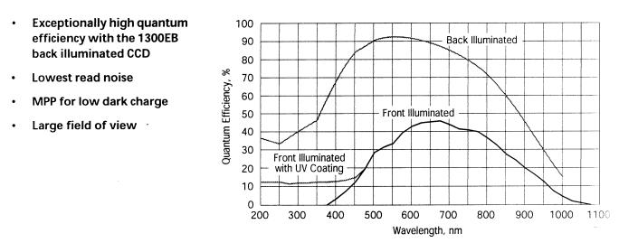
The detector is an EEV LN/1300-EB/1 CCD with 1300 x 1340 pixels, AR Visar coated, back illuminated.
Each wheel has eight positions. Filters and grisms wheels are mounted in the parallel beam area, between the collimator and the camera, while the slits wheel is mounted on the telescope focal plane.
Between the filters and grisms wheels is installed a wheel acting as shutter for the CCD. The optical axis of the instrument is tilted 110° with respect to the telescope optical axis, in order to reduce instrument dimensions and increase its stiffness.
A BFOSC scheme is shown here:
3.
INSTRUMENT CHARACTERISTICS
*using EEV CCD.
In case of problems with the EEV CCD a backup detector is available. This CCD, a Thomson xxxx, has 1024 x 1024 pixels with a field of 9.6' x 9.6' and a sampling of 0.562 arcsec/pix.
3.1 Optics
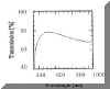
Optics have been built using FK54 and UBK7 galsses. This in order to give a good transmission (cut-off at 360 nm) in the UV. Optics have been coated with a single layer of MgF2, centered to 500 nm, to improve anti-reflection characteristics. Reflection losses are ~ 1.5% at central wavelength and increase to ~ 2.5% at the extremes. The following graph shows the optics transmission.
3.2 Slits Wheel
The slit wheel, mounted on the telescope focal plane, can hold seven different slits, beeing one of the apertures intentionally left empty to allow direct image acquisition. At present four different slits are available: 1.5", 2", 2.5" and 5", a special 2" slit for echelle spectra and a mask to be used for polarimetry.
The slit length is large as the usable field while the echelle slit is 9" long.
3.3 Filters Wheel
Like the slits wheel, also the filters wheel has seven available positions. At present can be mounted:
U, B, V, R, I Johnson-Kron-Cousin filters
G, R, Z, I Thuan-Gunn filters.
On the filters wheel can also be mounted the cross-disperser (#10, #11, #12) used with the echelle grism #9 to allow medium dispersion spectroscopy. A differential filter, used as order separator, is mounted on the filter wheel in conjuction with the grism #13. Two Hartmann masks can also be mounted to control the camera focusing.
3.4 Grisms Wheel
The available grisms are more than the number of positions on the wheel itself (7 as usual). Let us see in detail their characteristics:
*Grism #4 has a "free spectral range" smaller than the value shown in the table. In fact the table shows the first order spectral coverage but the range free from second order overlap ends at 700 nm.
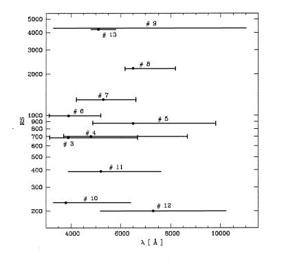
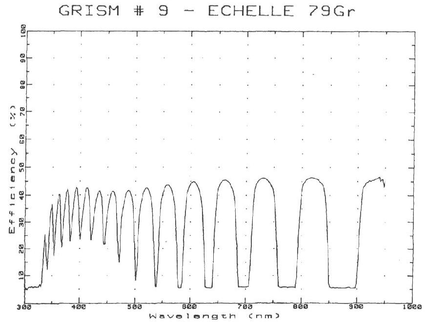
Grisms #10 , #11, and #12 are cross-dispersers to be used mainly with echelle grism #9 and are mounted on the filters wheel. They are optimized with respect to the working band: grism #10 has a peack efficiency in the blue, grism #11 in the visible and grsim #12 in the red. Also the number of orders on the detector varies with the cross-disperser: grism #10 gives 13 orders, grism #11 gives 9 orders and grism # 12 gives 6 orders.
In the following figure are shown the different grisms spectral range and resolution. The point indicate the blaze wavelenght.
3.5 SHUTTER AND FOCUSING THE CAMERA
BFOSC shutter has been made using a wheel, placed in the parallel beam area, that moves turning 90° each time. On it has been made two apertures allowing the light to reach the detector. The speed of the wheel is electronically controlled in such a way to keep constant the shutter speed rotation during the closing or opening phase. Acceleration and deceleration phases are timed to appen out of the CCD field of view.
For this reason there aren't illumination effect due to shutter movement.
Exposure times have a 0.1 sec resolution but the minimum exposure time is 3 seconds.
The camera is focused using the Hartmann masks mounted on the filters wheel. Since the camera focus change with temperature, a compensation table has been prepared. The camera focus procedure is known and under control of the tecnical personnel.
4 CALIBRATIONS LAMPS
Spectral wavelenght calibration is obtained through exposures of an Fe hollow-cathod lamp filled with He-AR.
Plots of the comparison spectrum in different configurations are shown in the Appendix 4.
5 CCD
The CCD mounted on BFOSC is an EEV LN/1300-EB/1 back illuminated and AR coated (Visar). The detector RON is 3.06 e-/pix and the gain is 2.22 e-/ADU. Normally the instrument has the slit oriented in E-W direction but it is possible to rotate the instrument in any direction (physical constrains to be taken into account). Dispersion is always along CCD columns.
6 OBSERVING PROCEDURES
The observer controls BFOSC using a PC that hosts the CCD controller and the BFOSC controller.
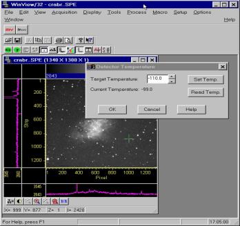
The WinView CCD control program allows to control the CCD image acquisition, the real-time image display and the BFOSC control.
In parallel to the WinView window is presented on the PC screen the BFOSC status window, that gives to the observer the updated instrument configuration. From the WinView window it is possible, using the BFOSC button, to access the BFOSC control window.
6.1 Focusing and Pointing
As previously said, BFOSC focusing is made using Hartmann masks. This is the camera focus with respect to the BFOSC focal plane. To focus the telescope on the BFOSC focal plane the suggestion is to obtain, at the beginning of the night, a set of exposures of a star at different telescope focus values (centered on the last used focus value) and examine the images using the IRAF procedure starfocus, on the reduction workstation in the control room. DO NOT CHANGE THE FOCUS USING THE CAMERA.
Exposure times should be not less than 15-20 sec. in order to have a good seeing measure.
In order to monitor seasonal seeing variations, observers are requested to measure seeing during the night (possibly using the IRAF psfmeasure command).
7 APPENDIX
7.1 Plots for Johnson-Kron-Cousin: U, B, V, R, I filters
7.2 Plots for Gunn: G, R, I, Z filters
7.3 Efficiency curves for grisms: #3, #4, #5, #6, #7, #8, #9E
7.4 Plots for the He-Ar calibration lamp for the different configurations:
#3, #4, #5, #6, #7, #8, #9E
Suggested exposure times for spectral calibration lamp:
| Collimator focal lenght | 252.1
mm |
| Collimator linear field | 52.9 x 52.9 mm |
| Beam diameter | 31.5 mm |
| Camera focal lenght | 146.3 mm |
| Camera linear field | 30.7 x 30.7 mm |
| Reduction ratio | 0.58
|
| Spectral range | 330 - 1100 nm |
| Maximum spectral resolution | 4200
|
| Projected pixel dimension | 0.58 arcsec/pix* |
| Field dimension | 13'
x 12.6'* |
*using EEV CCD.
In case of problems with the EEV CCD a backup detector is available. This CCD, a Thomson xxxx, has 1024 x 1024 pixels with a field of 9.6' x 9.6' and a sampling of 0.562 arcsec/pix.
3.1 Optics
Optics have been built using FK54 and UBK7 galsses. This in order to give a good transmission (cut-off at 360 nm) in the UV. Optics have been coated with a single layer of MgF2, centered to 500 nm, to improve anti-reflection characteristics. Reflection losses are ~ 1.5% at central wavelength and increase to ~ 2.5% at the extremes. The following graph shows the optics transmission.
3.2 Slits Wheel
The slit wheel, mounted on the telescope focal plane, can hold seven different slits, beeing one of the apertures intentionally left empty to allow direct image acquisition. At present four different slits are available: 1.5", 2", 2.5" and 5", a special 2" slit for echelle spectra and a mask to be used for polarimetry.
The slit length is large as the usable field while the echelle slit is 9" long.
3.3 Filters Wheel
Like the slits wheel, also the filters wheel has seven available positions. At present can be mounted:
U, B, V, R, I Johnson-Kron-Cousin filters
G, R, Z, I Thuan-Gunn filters.
On the filters wheel can also be mounted the cross-disperser (#10, #11, #12) used with the echelle grism #9 to allow medium dispersion spectroscopy. A differential filter, used as order separator, is mounted on the filter wheel in conjuction with the grism #13. Two Hartmann masks can also be mounted to control the camera focusing.
3.4 Grisms Wheel
The available grisms are more than the number of positions on the wheel itself (7 as usual). Let us see in detail their characteristics:
| Grism
# |
L
blaze (nm) |
L
grism (nm) |
Dispersion (nm/mm) |
D
L (nm) |
LL
EEV (nm) |
LL
Thom. (nm) |
L/pix
EEV (nm/pix) |
| 3 |
390 |
430 |
17 |
0.55 |
330
÷ 642 |
330
÷ 580 |
0.27 |
| 4 |
480 |
580 |
22 |
0.83 |
380
÷ 470 |
394
÷ 786* |
0.40* |
| 5 |
650 |
700 |
22 |
0.75 |
480 ÷ 980 | 520
÷ 905 |
0.40 |
| 6 |
390 |
400 |
11 |
0.39 |
330
÷ 535 |
330
÷ 495 |
0.17 |
| 7 |
530 |
525 |
11 |
0.41 |
420
÷ 600 |
430
÷ 625 |
0.10 |
| 8 |
650 |
700 |
8.8 |
0.30 |
610
÷ 818 |
620
÷ 785 |
0.10 |
| 9 Ech |
17 orders |
2.6 |
0.12 |
350
÷ 1020 |
335
÷ 940 |
||
| 10 C. D. |
380 |
390 |
46 |
1.7 |
330
÷ 640 |
||
| 11 C.D. |
520 |
500 |
34 |
1.3 |
400
÷ 700 |
||
| 12 C.D. |
730 |
700 |
91 |
3.7 |
530
÷ 1020 |
||
| 13 |
510 |
525 |
3.6 |
0.12 |
495
÷ 560 |
||
*Grism #4 has a "free spectral range" smaller than the value shown in the table. In fact the table shows the first order spectral coverage but the range free from second order overlap ends at 700 nm.
Grisms #10 , #11, and #12 are cross-dispersers to be used mainly with echelle grism #9 and are mounted on the filters wheel. They are optimized with respect to the working band: grism #10 has a peack efficiency in the blue, grism #11 in the visible and grsim #12 in the red. Also the number of orders on the detector varies with the cross-disperser: grism #10 gives 13 orders, grism #11 gives 9 orders and grism # 12 gives 6 orders.
In the following figure are shown the different grisms spectral range and resolution. The point indicate the blaze wavelenght.
3.5 SHUTTER AND FOCUSING THE CAMERA
BFOSC shutter has been made using a wheel, placed in the parallel beam area, that moves turning 90° each time. On it has been made two apertures allowing the light to reach the detector. The speed of the wheel is electronically controlled in such a way to keep constant the shutter speed rotation during the closing or opening phase. Acceleration and deceleration phases are timed to appen out of the CCD field of view.
For this reason there aren't illumination effect due to shutter movement.
Exposure times have a 0.1 sec resolution but the minimum exposure time is 3 seconds.
The camera is focused using the Hartmann masks mounted on the filters wheel. Since the camera focus change with temperature, a compensation table has been prepared. The camera focus procedure is known and under control of the tecnical personnel.
4 CALIBRATIONS LAMPS
Spectral wavelenght calibration is obtained through exposures of an Fe hollow-cathod lamp filled with He-AR.
Plots of the comparison spectrum in different configurations are shown in the Appendix 4.
5 CCD
The CCD mounted on BFOSC is an EEV LN/1300-EB/1 back illuminated and AR coated (Visar). The detector RON is 3.06 e-/pix and the gain is 2.22 e-/ADU. Normally the instrument has the slit oriented in E-W direction but it is possible to rotate the instrument in any direction (physical constrains to be taken into account). Dispersion is always along CCD columns.
| EEV
CCD CHARACTERISTICS |
|
| Detector |
EEV
LN/1300-EB/1 |
| Controller |
Photometrics
Series ST133B/100 KHz and 1 MHz |
| Array |
1300x1340
pixels |
| Special Features |
coating
AR Visar, back illuminated |
| Quantum Efficiency |
80%
@ 500 nm, 32% @ 900 nm, >50% @ 300 nm |
| Pixel size |
20x20
micron |
| Pixel scale |
0.58
arsec/pixel |
| Field of view |
13'x12.6' |
| Read-out time |
2
sec @ 1 MHz, 18 sec @ 100 KHz ( standard work: 100KHz ) |
| Read-out noise |
3.06
e-/px @ 100 KHz (
standard work: 100 KHz ) |
| Conversion factor |
2.22
e-/ADU @ 100 KHz |
| Dynamical range |
16
bit |
| Full-well capacity |
Sensitivity
mode: 117000 elettrons |
| Response
non-linearity |
<
1% for 16 bit @ 100 Khz |
| Response
non-uniformity |
<
± 4% over entire ccd area |
| Operating
temperature |
-100
°C |
| Image processing
software |
Winview,
on line |
| Output data format |
Fits |
| Image dimension |
3.5
Mbyte |
| Typical dark charge |
15.1 e-/pixel-hour at -97°C |
| Liquid nitrogen hold time |
~
12 hours |
6 OBSERVING PROCEDURES
The observer controls BFOSC using a PC that hosts the CCD controller and the BFOSC controller.
The WinView CCD control program allows to control the CCD image acquisition, the real-time image display and the BFOSC control.
In parallel to the WinView window is presented on the PC screen the BFOSC status window, that gives to the observer the updated instrument configuration. From the WinView window it is possible, using the BFOSC button, to access the BFOSC control window.
6.1 Focusing and Pointing
As previously said, BFOSC focusing is made using Hartmann masks. This is the camera focus with respect to the BFOSC focal plane. To focus the telescope on the BFOSC focal plane the suggestion is to obtain, at the beginning of the night, a set of exposures of a star at different telescope focus values (centered on the last used focus value) and examine the images using the IRAF procedure starfocus, on the reduction workstation in the control room. DO NOT CHANGE THE FOCUS USING THE CAMERA.
Exposure times should be not less than 15-20 sec. in order to have a good seeing measure.
In order to monitor seasonal seeing variations, observers are requested to measure seeing during the night (possibly using the IRAF psfmeasure command).
7 APPENDIX
7.1 Plots for Johnson-Kron-Cousin: U, B, V, R, I filters
7.2 Plots for Gunn: G, R, I, Z filters
7.3 Efficiency curves for grisms: #3, #4, #5, #6, #7, #8, #9E
7.4 Plots for the He-Ar calibration lamp for the different configurations:
#3, #4, #5, #6, #7, #8, #9E
Suggested exposure times for spectral calibration lamp:
|
#3 |
30 sec |
| #4 |
7 sec |
| #5 |
6 sec |
| #6 |
50 sec |
| #7 |
50 sec |
| #8 |
8 sec |
| #9 |
8 sec |